

|
|
|
Phone (603) 974-2183
|
Hayabusa Factory Pro Shift Star
Installing the Factory Pro Shift Kit in a Gen II GSX1300R Hayabusa
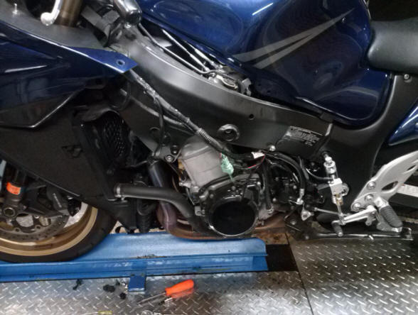
We started with the bike cleaned and rather than put it on a lift or work on it on the floor, ours is on the dyno.
Remove the left side fairing. On the Gen II there is no coolant reservoir inside the fairing pocket like the Gen 1's.
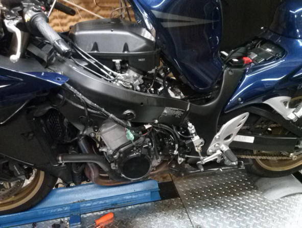
It's also a good idea to prop up the tank to gain access from above. This will help with wire routing. You are going to lose a half a quart of oil when you pull the shift actuator cover. You may want to drain the oil now. If not be prepared with a catch can when you pull the shift actuator cover later on.
Start by breaking the hardware free for sidestand removal. Also note that the bike in the example has an air-shifter installed, so the cylinder will be unbolted and the wires to the solenoid and the air line have to pulled as well.
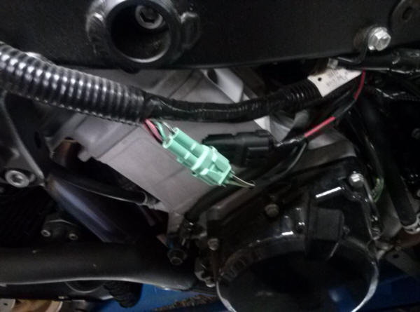
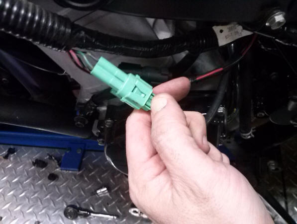
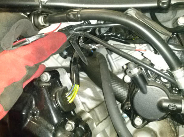
Next you will deal with these two connectors.
Press down on the tab to unlock and disconnect.
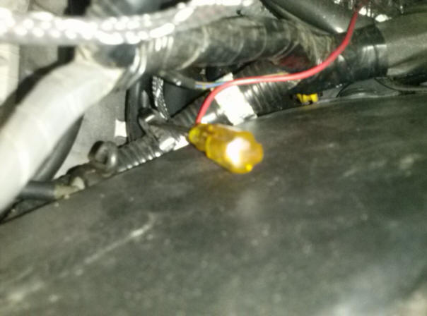
Look for this cable tie. It can be loosened by fitting a small screw driver into the back of the lock. Loosen this to allow the connectors that we remove to pass through aiding in parts removal.
Not a great photo, but you get the idea. Slide screw driver into the back of the cable tie lock and it can be slackened. pass the side stand connector through, remove the side stand bolts and set aside.
I had to use an impact gun to get the side stand bolts out. Yours may be easier than mine.
This is the connector from the road speed pulse generator. call it the speedo connector. Lift up on the tab to disconnect this one. Feed it back to the sprocket cover clutch slave cylinder cover.
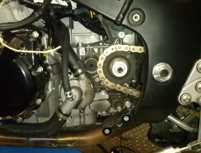
Remove the four 8 mm hex head bolts. The slave cylinder comes out with the cover. it can help to slide a screw driver or other pray tool up from the bottom and gently prying between the sprocket and bottom, while pulling straight out on the top. Don't pry the crap out of it, just enough to get it to come straight off the dowels.
I tied this to the frame since the clutch line is still attached and it held it out of way just fine.
On a Gen II you do NOT need to remove the chain and sprocket. You can get to everything with the sprocket in place.
At this point I spent quite a while cleaning up all the chain lube mess. This junk is full of sandy debris and you don't want any of this getting inside you engine. use plenty of WD-40 and the solvents will cut the chain lube nicely.
I pulled out my clutch push rod and filled the hole in the seal with a shop towel end.
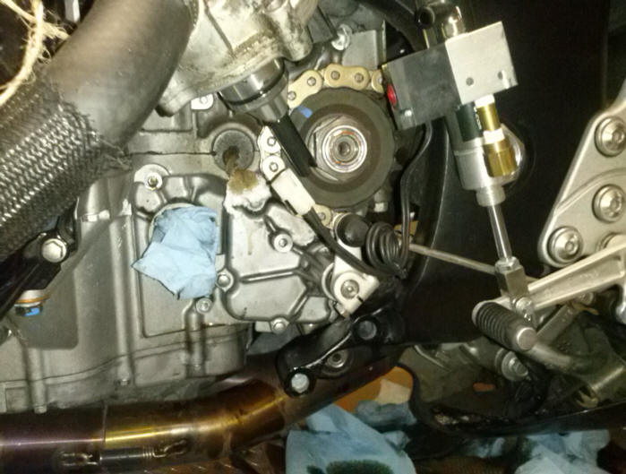
When everything is clean remove the two 8mm socket heads on the water pump. You can drain the system and remove the pump or just tie it back out of the way. be careful not to get any dirt in the water pump through hole. You can see the angle of the slot in the drive. This needs to match up to the pump drive shaft when re-installing. Make note of this now.
Here you can see I've tied the water pump out of the way and have plugged the water pump hole with a shop towel. The little box under the sprocket is our goal. It has Qty 5 hex head bolts holding it in place. WARNING!!! The one behind the side stand its an absolute pain in the ass to remove. I tried grinding down a wrench - No workie. I ground down a socket so it was short enough to slip behind the frame - No workie. None of my offset box end wrenches had a small enough head - so....I drove the bitch out with a chisel. I drove the bottom counter clock wise until she snapped free. Then she came right out. This bolt will not come out on it's own. It has to be slipped out with the cover and will need to be installed with the cover in the same fashion. I used a Dremel tool and cut an X in the head of the tough to reach screw to aid in reassembly.
Note: This is the cover that will dump the oil if you haven't drained already.
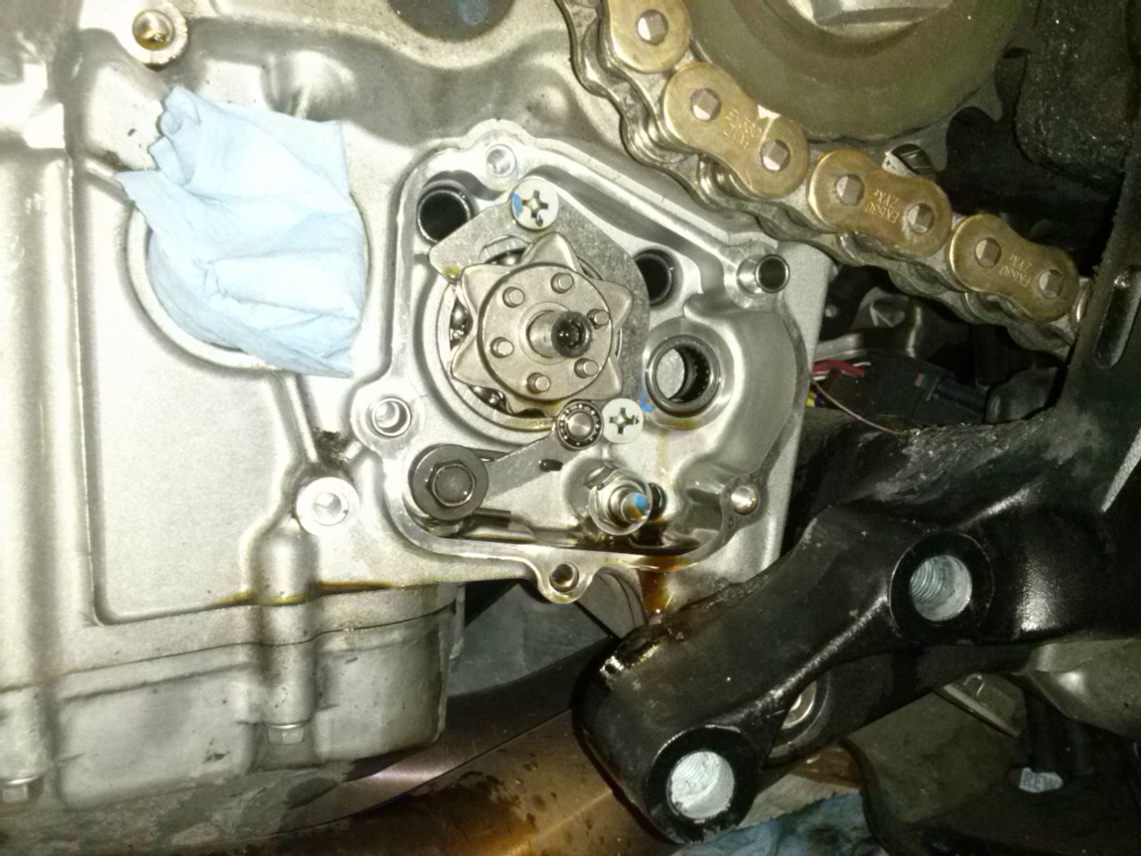
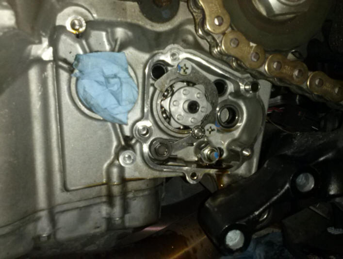
Here is the star and the lever arm. Remove the arm first. It's a right hand thread. pry down on the arm with a screw driver during removal.
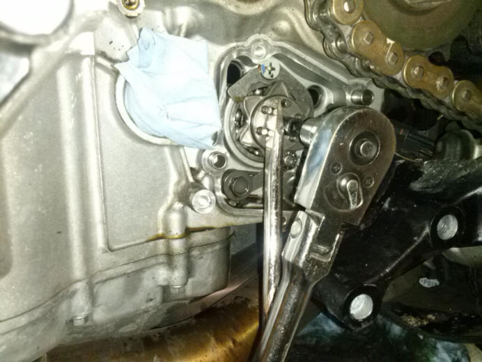
There us a socket head cap screw holding the shift star in place. It is also a conventional right hand thread.
Use a screw driver to hold the star and shift drum still while you remove the retaining screw. If you don't you will be forcing the load through the shift drum and forks and probably wind up with a bike that won't shift. Be careful here.
Here is the Factory Pro star and spring installed. Make sure the two legs of the spring on the shift shaft are on each side of the peg (mine has a big blue drop of glyptol on it from the factory) when you reinstall the cover. You can reach up inside with your index finger when reinstalling and feel where the two legs of the spring are located. The shaft pushes in and gives you a little room to work with. Just don't push too far or the shaft will pop all the way through the cover.
before you bolt everything back up, hook up your shift linkage and test the shifting. Make sure you can spin the rear wheel or at least jog it back and forth. Otherwise the bike will not cycle in and out of gear. It's almost impossible for the shift dogs to line up with every gear selection, so a little rotation is necessary. if it doesn't shift, you'll know long before you button everything up. Bolt everything back together in the reverse order and test it out. You'll find you have a much better shifting Busa. We accept Visa, Master Card, American Express and Discover through Square. Of course we still gladly accept cash payment too!
|
|
Send mail to
elizabeth@viciouscycletuning.com with questions or comments about this web
site.
|